CAKE 2/27

CAKE notes Feb 27 2016
Those who follow these notes will appreciate the difficulty of finding adequate superlatives for our many presentations. Glenn N6GN, aided by John K6PZB and Bob W6SFH, were quite outstanding. They are exceptionally well qualified retired engineers from HP in it?s hey-day, with an incredible record of inventing, making and patenting radio and measuring equipment, they traveled all the way from Santa Rosa to be with us. Their subject was SWTL (which can equally stand for Surface Wave or Single Wire Transmission line). SWTL transmission is a radical departure from the behavior of guided wave lines typified by coaxial cable or parallel open wire line.
Our very attentive audience included Warren NR0V, Peter K6UNO, Bob K6XX, Kerry K3RRY, Fred KJ6OOV and Ward AE6TY. It was a pleasure to see Eric K6EP after too long an interval.
Glenn well understands the skepticism engendered by SWTL and listed a number of questions that he often hears. We were invited to pick those questions which the audience saw as foremost in their minds. One that struck a chord with some was ?why does a single wire carrying RF current not radiate?. It was explained that it uses a mode of propagation where only the magnetic field is transverse to the direction of transmission, labeled TM, whereas what we normally experience is a mode, labeled TEM, where both electric and magnetic fields are transverse. A wave propagated in free space requires requires an antenna carrying both E and M components therefore the SWTL line doesn?t radiate a free space wave. To fully understand the physics involved requires a deeper understanding which was beyond the scope of Glenn’s Part 1 of his SWTL story.
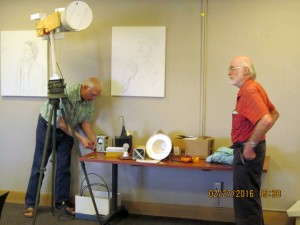
Their impressive demo involved about 20 ft of thin copper wire at 7 ft above the floor terminated in what appears to be horn-shaped antennas. These are called launchers which couple a conventional 50 Ohm coax line and source of RF to the wire and interface a 50 Ohm dummy load and wattmeter at the receiving end. For demo purposes, the incoming RF is rectified to DC and used to light a 100W lamp bulb. With 80W of RF at 2M the watt meter registered 40 W and the bulb glowed brightly. The path loss over the wire was 3 dB whereas without the wire it would probably have exceeded 40dB. Here Glenn and Bob are setting up the receiving end of the demo.
Here a schematic of a typical (not identical to our demo).
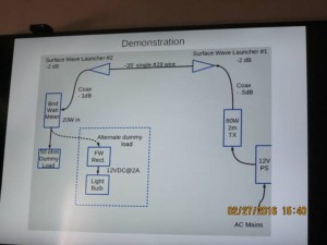
Glenn said that launcher to launcher path loss without the wire in our demo would have been about 40 dB where as the end-end loss in the demo was less than 6dB. Notice that they sent 2m RF via a single wire and ended with enough power to brightly light a lamp bulb.
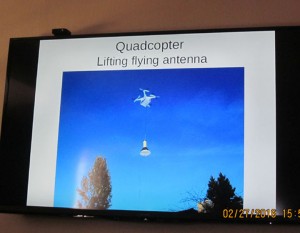
Glenn illustrated one possible use of a SWTL is to supply sufficient energy to power the motors and electronics of a tethered drone, In this way it could stay aloft indefinitely.
his is feasible in part because of the very low weight of the wire, and launchers (made from metalized paper), These are precision devices which required the combined engineering and artistic talents of our guests. Glenn has published his work widely and in in particular QEX 2012 May/June, July/August and Nov/Dec For our benefit Glenn has placed his presentation material on his site sonic.net/~N6GN/CAKE/CAKE.
http://www.sonic.net/~n6gn/CAKE/CAKE.pdf
Stay tuned for the next two CAKE sessions on March 12 and 26th
73 Ron
————————–
Ron and all,
Thanks for sending and hosting us. Just for clarification on a couple of your notes, should anyone be interested:
John, K6PZB, is not ex-HP, rather he chaired the Art Department at Santa Rosa Junior College for 25 years!
It’s not the lack of TEM that prevents radiation, coax has that, it’s the presence of symmetry that causes far fields to cancel. This is discussed in the “Introduction…” paper and shown in the lilnked animation of the field solution available in the PDF.
While the demo launchers I used were hornlike, the Depron version I showed (and is shown on the table and in the recent video) is not.Note it has a small square mouth.
The loss with the wire absent or substantially removed even at the distance we had would likely have been more than 60 dB. It’s really irrelevant since launchers aren’t antennas.
The schematic is actually almost exactly the demo, though I didn’t measure the actual separation.
Note that in addition to keeping a quadcopter aloft permanently, this system creates a skyhook which can support antennas also fed by this same low-loss transmission line. Thus one gets antennas at very significant altitude along with 40-60 dB “height gain” in a majority of VHF-microwave circumstances.
Important: Note that the correct URL has a “.pdf” extension and should be: http://www.sonic.net/~n6gn/CAKE/CAKE.pdf
To get more of the physics, have a look at “Introduction to the Propagating Wave on a Single Conductor”, I think that may help with some of your questions and show some modelling that discusses displacement currents – something you asked about.
Thanks again for your kind hospitality and words. I hope we may all meet again when CAKE reciprocates and possibly for a Part 2.
Best
Glenn n6gn